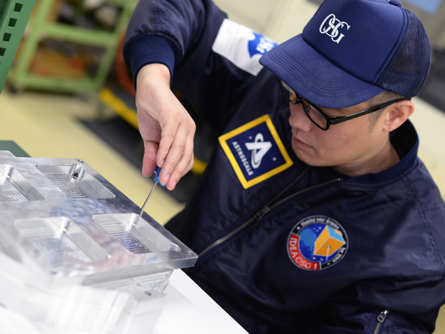
Construction of IDEA OSG 1
Orbital Debris Monitoring “IDEA OSG 1”
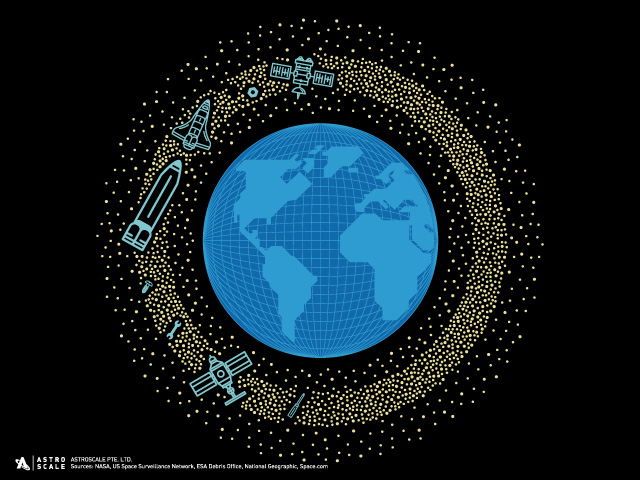
IDEA OSG 1 is a microsatellite that will measure small-size debris orbiting the earth — this comprises debris the size of grains of sand (0.1 to several mm). ASTROSCALE is developing the IDEA OSG 1 based on a concept born in the Hanada Laboratory at Kyushu University. Micro-debris has the potential to inflict lethal damage on satellites, and yet neither its distribution nor quantities are fully known, and as such, a better understanding of this debris, as well as tracking are required. The mission of “IDEA OSG 1” is to dynamically construct a micro-debris environmental model (a model defining the distribution and current quantities of debris) from micro-debris measurement data, and to use this in formulating measures to both counter debris in the design of spacecraft, and minimize collision damage.
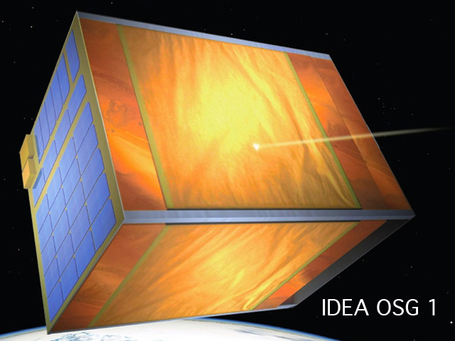
The 20kg micro satellite “IDEA OSG 1” with a compact envelop (38 cm x 38 cm x 60 cm) is equipped with two pieces of micro-debris impact sensor known as “Space Debris Monitors (SDM)”. SDM is developed by the Japan Aerospace Exploration Agency (JAXA) based on the shared patents by Institute for Q-shu Pioneers of Space, Inc. and IHI Corporation. A single SDM has a measurement area of approximately 1,000 cm2 that detects impacts of micro-debris in almost real-time. Impacted micro-debris will be absorbed by the IDEA OSG 1 through the satellite structure. The impact sensing part of SDM consists of the polyimide film where approximately 3,300 conductive stripes 50 μm wide are printed at 100 μm intervals. Micro-debris penetrates the SDM to creates holes at every impact, thereby severing the conductive stripes. The size of the actual micro-debris impacting SDM is estimated from the number of severed conductive stripes. This measurement technique applied to SDM does not require a sensor calibration model for each individual impact sensors produced, which is normally required for ordinary impact sensors, so that a standardized measurement system can be achieved via constructing a constellation of satellites equipped with SDM.
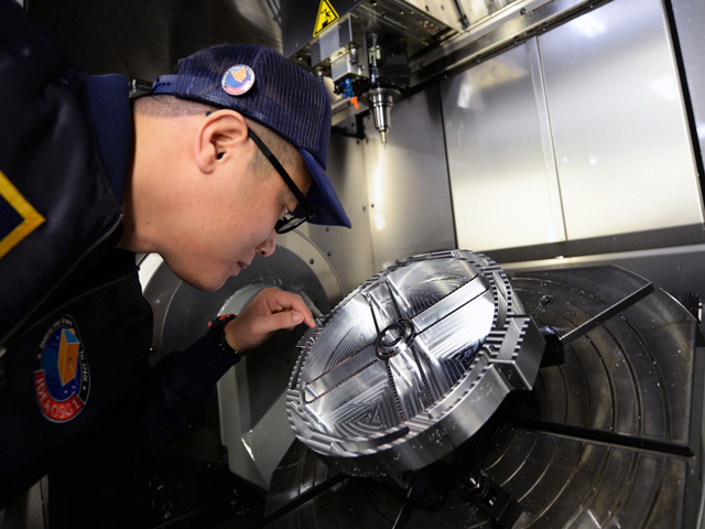
OSG Machined Parts
Flange Ring
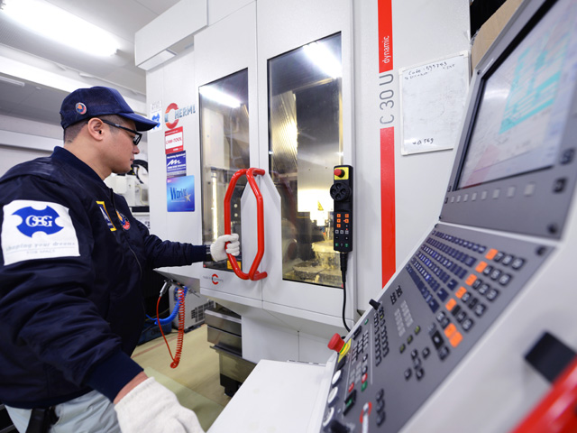
We interviewed Application Engineer Yasuhito Fujii from the OSG’s Product Development Division on the machining of the flange ring, which is a part of the “IDEA OSG 1” satellite.
- What did you find difficult about machining the flange ring?
- There are three key questions we should ask ourselves before machining a product – from what direction? With what tool? And using what machining method?
- With this project, the part that is difficult to machine is the round shape of the “ring,” as it is popularly known. It must be finished with a high degree of precision from multiple directions. Furthermore, this ring is designed with consideration given to producing a lightweight and balanced final product. In other words, the more that is cut from the product, the less rigid it becomes. In such conditions, selecting a jig design and processing method to ensure thorough machining is difficult. There are cases in which deformation occurs when the product is removed from the jig, and in such a case, this deformation may throw off the overall accuracy of the part, leading to it being rejected.
- Is there anything unique that you do when making a part?
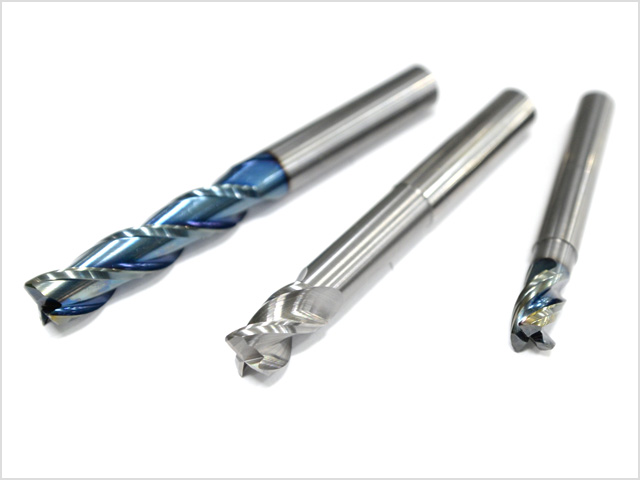
- As a tool manufacturer, OSG is in possession of numerous standard catalog tools. However, in the machining of this ring, we used tools currently in development, and specialized tools that match the part shape to create an even better product. Undertaking this type of part creation in-house proves useful in developing new products.
- What requires the most attention in part machining?
- Machining accuracy. Although accuracy is checked with machining equipment, if a three-dimensional measurement inspection is not cleared, then the product is rejected.
- What skills are needed in part machining?
- The ability to operate machinery, to use CAD/CAM, and to design equipment such as jigs.
- What are the special characteristics of the machining equipment?
- For the machining of the flange ring, we used a German five-axis machining center. We are not concerned with the country of manufacture, but rather look for machines with dependable accuracy.
- How many tools did you use in machining the ring?
- We used 18 types of tools. Out of which, five are custom-made tools.
- What materials are used to make the flange ring?
- Aluminum alloy. It is actually known as “extra super Duralumin.” Aging treatment is applied to the extra super Duralumin to increase strength and hardness.
- Is it difficult to machine extra super Duralumin?
- Much like heat-resistant alloys, extra super Duralumin has good machinability, so it is not difficult to machine if sufficient cutting oil is applied. However, the characteristics of the material mean that the rate of thermal expansion is high, and applying excessive heat or force to the product during the cutting process may cause deformation. So we have to take that into consideration during the machining process.